Even as SLIP was being documented as a "nonstandard" in RFC 1055, work was
underway for a newer protocol to provide full-featured IP transmission over
direct links between pairs of devices. The result is the Point-to-Point
Protocol (PPP), which defines a complete method for robust data link
connectivity between units using serial lines or other physical layers. It
includes numerous capabilities and features, including error detection,
compression, authentication, encryption and much more.

Even though PPP is called a "protocol", and even though it is considered
part of TCP/IP depending on whom you ask it is really more a protocol suite
than a particular protocol. The operation of PPP is based on procedures
defined in many individual protocols, as we will see in this section. Thus,
PPP can be considered a "protocol suite within a protocol suite"
Alternately, its components can be viewed as "subprotocols" within PPP.

In this section I provide a comprehensive look at the operation of the
Point-to-Point Protocol, in four subsections. The first describes the
fundamentals of PPP, including its history, standards and an overview of
its general operation. The second explains the .core. protocols that are
responsible for setting up PPP links and basic operation. The third covers
the protocols used to implement various special features in PPP, such as
compression and encryption. The last subsection provides detailed
information on the various frame formats used by PPP protocols.


PPP FUNDAMENTALS AND OPERATION

The problem with the Serial Line Internet Protocol was that it was too
simple and didn't include enough features. As the saying goes, "be careful
what you wish for", especially when the complaint is too much simplicity.
The Point-to-Point Protocol (PPP) corrects the lack of features in SLIP,
but you could figure out, without really trying, what the cost is:
significantly more complexity. Where the operation of SLIP can be explained
in a few paragraphs, PPP is much more involved, including a number of
specific processes that need to be explained.

Before discussing the individual protocols that comprise PPP, I want to
take a high-level look at the protocol suite. I start with an overview,
history and discussion of the benefits of PPP. I provide a high-level
breakdown of the main components of the PPP suite, and a general
description of how PPP operates. I then describe the steps involved in
setting up and configuring a link, and the phases a PPP link passes
through during its .lifetime.. Finally, I categorize and list the
standards that define different aspects of PPP's functionality.


IPPP OVERVIEW, HISTORY AND BENEFITS

Albert Einstein is credited with the following quote: "Everything should
be made as simple as possible - but no simpler". The Serial Line Internet
Protocol (SLIP) is a good example of this maxim. It provides basic layer
two framing for IP, but it is just too simple for many uses. Since all it
does is frame the end of each datagram, it doesn't provide many of the
features that we really need for reliable, secure and high-performance
operation over serial links. This is especially true today when most
serial connections are not short LAN cables but dial-up WAN connections
over relatively long distances.


PPP Development and Standardization

SLIP was basically a "hack" to fill a specific need: bridging the gap
between IP at layer three and a serial link at layer one. It "gets the job
done" but doesn't provide any of the features we really want in a robust
protocol for direct links between devices. PPP was developed to be a
complete protocol suite that would enable fully-functional layer two
connectivity to support not just IP but the transmission of other network
layer protocols as well.

The history of PPP goes back to the late 1980s, when SLIP was the de facto
standard for serial IP implementations. The first formal IETF document related
to PPP was RFC 1134, published in 1989. This RFC is not the standard itself
but a proposal for what would eventually be defined as the first main PPP
standard, RFC 1171, in 1990. This early document has been revised several
times and several other documents added that define the various protocols
that comprise the entire PPP suite. PPP standards are described later in
this section.

The IETF is always smart about not reinventing the wheel. Rather than try
to develop PPP from scratch, the decision was made to base it on the ISO
High-Level Data Link Control (HDLC) protocol, which was initially developed
by IBM. HDLC is a derivative of the Synchronous Data Link Control (SDLC)
protocol. PPP's developers adapted its framing structure and some of its
general operation from the HDLC protocol.


PPP General Function and Architecture

PPP is a connection-oriented protocol that enables layer two links over a
variety of different physical layer connections. It is supported on both
synchronous and asynchronous lines, and can operate in half-duplex or
full-duplex mode. It was designed to carry IP traffic but is general enough
to allow any type of network layer datagram to be sent over a PPP connection.
As its name implies, it is for point-to-point connections between exactly
two devices, and assumes that frames are sent and received in the same order.

PPP fits into the Network Interface layer (Link Layer) in the TCP/IP model,
as shown in Figure 23. The operation of PPP follows a specific sequence
described in the general operation topic, including a multi-step link
establishment phase that may include optional authentication.
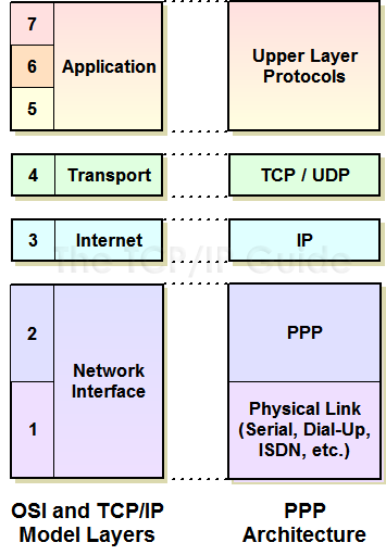
Figure 23: PPP Location in TCP/IP Architecture

PPP acts as the interface between the Internet Protocol and a physical link
such as a serial line or dial-up networking connection. This corresponds to
layer two in the OSI Reference Model.


PPP Advantages and Benefits

A list of PPP's strengths reads very much like a list of SLIP's weaknesses,
which I explained in detail in the topic on SLIP. Some of the specific
benefits of PPP compared to SLIP include:

* A more comprehensive framing mechanism, compared to the single END
character in SLIP.

* Specification of the encapsulated protocol, to allow multiple layer
three protocols to be multiplexed on a single link.

* Error detection for each transmitted frame through the use of a CRC
code in each frame header.

* A robust mechanism for negotiating link parameters, including the
maximum frame size permitted.

* A method for testing links before datagram transmission takes place,
and monitoring link quality.

* Support for authentication of the connection using multiple authentication
protocols.

* Support for additional optional features, including compression,
encryption and link aggregation (allowing two devices to use multiple
physical links as if they were a single, higher-performance link).

The proliferation of serial links, especially for dial-up Internet access,
has led to widespread use of PPP. It is now one of the most popular layer
two WAN technologies in the networking world, and has replaced SLIP as the
standard for serial connections on all but legacy implementations. While
most often associated with dial-up modem use, PPP can run across any similar
type of physical layer link. For example, it is often used to provide layer
two functionality on ISDN B channels.

Key Concept: PPP is a complete link layer protocol suite for devices using
TCP/IP, which provides framing, encapsulation, authentication, quality
monitoring and other features to enable robust operation of TCP/IP over a
variety of physical layer connections.


PPP's Extensibility

A key advantage of PPP is that it is an extensible protocol suite. Over the
years new protocols have been added to the suite, to provide additional
features or capabilities. For example, PPP is designed not to use just a
single authentication protocol, but to allow a choice of which protocol is
used for this purpose.

PPP's success has even led to the development of derivative protocols like
PPP over Ethernet (PPPoE) and PPP over ATM (PPPoA). These actually layer PPP
over existing data link layer technologies, which shows you how valued PPP's
features are - even when a layer two technology is already in use, applying
PPP on top provides authentication and management benefits for services like
DSL.


PPP COMPONENTS AND GENERAL OPERATION

Ptands for the Point-to-Point Protocol, but even the standard that defines PPP immediately starts describing protocols that comprise it, which is why I consider it a protocol suite. At the highest level, the functions of PPP can be broken down into several components. Each of these encompasses a general class of PPP functionality, and is represented by either one protocol in the suite or a set of protocols.
Main PPP Components

The PPP standard itself describes three main components of PPP:

* PPP Encapsulation Method: The primary job of PPP is to take higher-layer
messages such as IP datagrams and encapsulate them for transmission over
the underlying physical layer link. To this end, PPP defines a special
frame format for encapsulating data for transmission, based on the framing
used in the HDLC protocol. The PPP frame has been specially designed to
be small in size and contain only simple fields, to maximize bandwidth
efficiency and speed in processing.

* Link Control Protocol (LCP): The PPP Link Control Protocol (LCP) is
responsible for setting up, maintaining and terminating the link between
devices. It is a flexible, extensible protocol that allows many configuration
parameters to be exchanged to ensure that both devices agree on how the
link will be used.

* Network Control Protocols (NCPs): PPP supports the encapsulation of
many different layer three datagram types. Some of these require additional
setup before the link can be activated. After the general link setup is
completed with LCP, control is passed to the PPP Network Control Protocol
(NCP) specific to the layer three protocol being carried on the PPP link.
For example, when IP is carried over PPP the NCP used is the PPP Internet
Protocol Control Protocol (IPCP). Other NCPs are defined for supporting
the IPX protocol, the NetBIOS Frames (NBF) protocol, and so forth.

The PPP encapsulation method and LCP are defined in the main PPP standard
and some support standards; the NCPs are described in separate standard
documents, one per NCP.  Additional PPP Functional Groups

While the three components above do constitute much of the total package of
PPP, I would add to the list of components in the standard two additional
functional groups. These represent some of the many extra protocols that
have been added over time to the suite to support or enhance the basic
operation of PPP:

* LCP Support Protocols: Several protocols are included in the PPP suite
that are used during the link negotiation process, either to manage it
or to configure options. Examples include the authentication protocols
CHAP and PAP, which are used by LCP during the optional authentication
phase.

* LCP Optional Feature Protocols: A number of protocols have been added
to the basic PPP suite over the years to enhance its operation after a
link has been set up and datagrams are being passed between devices. For
example, the PPP Compression Control Protocol (CCP) allows compression
of PPP data, the PPP Encryption Control Protocol (ECP) enables datagrams
to be encrypted for security, and the PPP Multilink Protocol (PPP MP)
allows a single PPP link to be operated over multiple physical links.
The use of these features often also requires additional setup during
link negotiation, so several define extensions (such as extra configuration
options) that are negotiated as part of LCP.

Each of these additional protocols is generally defined by a different
standards document. You can find a list of some of these in the topic on PPP
standards.  P's success has even led to the development of derivative protocols
like PPP over Ethernet (PPPoE) and PPP over ATM (PPPoA). These actually layer
PPP over existing data link layer technologies, which shows you how valued
PPP's features are.even when a layer two technology is already in use,
applying PPP on top provides authentication and management benefits for
services like DSL.  PPP's success has even led to the development of derivative
protocols like PPP over Ethernet (PPPoE) and PPP over ATM (PPPoA). These
actually layer PPP over existing data link layer technologies, which shows
you how valued PPP's features are.even when a layer two technology is already
in use, applying PPP on top provides authentication and management benefits
for services like DSL.  PPP's success has even led to the development of
derivative protocols like PPP over Ethernet (PPPoE) and PPP over ATM (PPPoA).
These actually layer PPP over existing data link layer technologies, which
shows you how valued PPP's features are.even when a layer two technology is
already in use, applying PPP on top provides authentication and management
benefits for services like DSL.


PPP General Operation

The fact that the PPP suite includes literally dozens of protocols often
makes it seem like it must be a really complex technology. In fact, the
general operation of PPP is really quite straight-forward. The existence of
all those PPP protocols allows PPP to be flexible and extensible, supporting
many higher layer datagram types and various features.

The bottom line, however, is that PPP operation involves just three basic
steps. Beginning in a state where there is no PPP link between the devices,
these are the operations that occur in PPP (also illustrated in Figure 24):

1. Link Setup and Configuration: Before the two devices can exchange
information, they must make contact and set up a link between them. During
link setup, all the parameters needed to manage the operation of the link
are agreed upon by the two devices. The LCP begins this process, and
invokes the help of support protocols as they are needed, for options
like authentication. After the link is set up in general terms, the
appropriate NCP is called for whatever layer three technology is being
carried on the link to complete link setup.

2. Link Operation: The devices on the link use it to send datagrams. Each
device transmits by taking layer three datagrams, encapsulating them and
sending them down to layer one to be transmitted. Each device receives
by taking PPP frames sent up from its own physical layer, stripping off
the PPP header and passing the datagram up to layer three. Where appropriate,
optional feature protocols are used here, such as CCP for compression.

3. Link Termination: When either device decides it no longer wants to
communicate, it terminates the link. The link can of course be re-established
if desired.
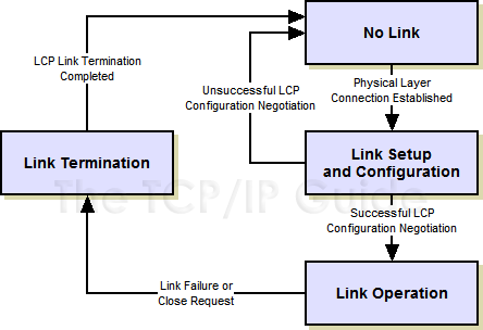
Figure 24: Overview of PPP Operation

In simplest terms, PPP consists of only three basic steps: link setup, link
operation and link termination.

Link setup is by far the most complicated of these general steps, as it
involves several substeps used to negotiate link parameters and options. The
next topic describes the steps in link setup, and discusses the phases that
a link passes through as it is set up, used, and eventually terminated.


PPP LINK SETUP AND PHASES

Before data can be exchanged on a PPP connection, a link must be set up
between the two devices. As part of this setup task, a configuration process
is undertaken whereby the two configure the link and agree on the parameters
for how data should be passed between them. Only after this is completed can
frames actually pass over the link.

The PPP Link Configuration Protocol (LCP) is generally in charge of setting
up and maintaining PPP links. LCP may invoke an authentication protocol (PAP
or CHAP) when PPP is configured to use authentication. After an LCP link has
been opened, PPP invokes one or more Network Control Protocols (NCPs) for
the layer three protocol being carried on the link. These perform any
network-layer-specific configuration needed before the link can carry that
particular network layer protocol.

The operation of a PPP link can be described as having a .life. of sort.
Just as humans are born, grow, have an adult life span and then die, a PPP
link is established, configured, used and eventually terminated. The process
of setting up, using and closing a PPP link is described in the PPP standard
as a series of phases or states. This is a type of finite state machine
(FSM), a tool used to explain the operation of protocols.


PPP Link Phases

When we talk about a PPP link overall, we are talking about the status of
the LCP connection between the two devices; again, LCP governs the overall
state of PPP as a whole. Once an LCP link has been opened, each of the NCPs
used on the link can be opened or closed independently of the overall PPP
(LCP) link. We'll see how this works momentarily.

An excellent way of understanding how PPP works is to look at these phases,
and the process by which transition is made from one to the next during the
lifetime of the link. For purposes of clarity, this description is based on
an example where device A is a PC performing a dial-up networking connection
to a remote host B (see Figure 25).
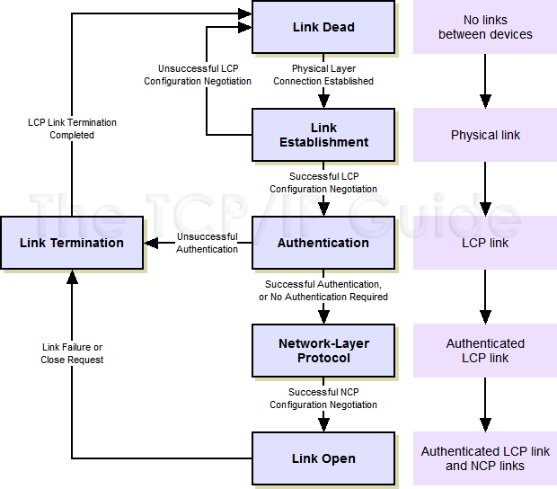
Figure 25: PPP Phases

The PPP connection between the two devices begins in the Link Dead state and
proceeds through three intermediate phases until the link is fully opened,
as shown in the flow chart on the left. It remains in the stable Link Open
phase until terminated. The purple boxes show the corresponding change in
the status of the PPP link as transitions are made between phases.


PPP LINK SETUP AND PHASES

Link Dead Phase

By design, the PPP link always begins and ends in this phase. This phase
represents the situation where there is no physical layer link established
between the two devices. It remains here until the physical layer link is
set up, at which point the link proceeds to the Link Establishment phase.

In our example, when A is first turned on, there is no physical layer
connection (modem connection) between it and B. Once the connection is made,
the link can proceed to phase 2. (Note that in a direct connection, such as
a serial cable linking two PCs, the link may only stay in the Link Dead phase
for a fraction of a second, until the physical layer connection is detected.)
Link Establishment Phase

The physical layer is now connected and LCP performs the basic setup of the
link. Device A sends an LCP configuration request message to device B over
the physical link, specifying the parameters it wishes to use. If Device B
agrees, it replies with an acknowledgement. If B doesn't agree, it sends
back a negative acknowledgment or rejection, telling device A what it won't
accept. Device A can then try a different configuration request with new
parameters that device B will hopefully accept. This process is described
in more detail in the topic covering LCP.

Hopefully, A and B will eventually come to agreement. If so, the status of
the link is considered LCP open, and will proceed to the Authentication
phase. If they cannot come to an agreement, the physical link is terminated,
and we go back to the Link Dead phase.


Authentication Phase

In many cases, a device may require authentication before it will permit
connection of another device. (This is certainly usually the case when PPP
is used for dial-up.) Authentication is not considered mandatory in PPP,
however. When it is used, the appropriate authentication protocol (CHAP or
PAP) is employed.

After successful authentication, the link proceeds to the Network-Layer
Protocol phase. If authentication is not successful, the link fails and
transitions to the Link Termination phase.  Network-Layer Protocol Phase

Once the basic link has been configured and authentication completed, the
general setup of the LCP link is complete. Now, the specific configuration
of the appropriate network layer protocol is performed by invoking the
appropriate NCP, such as IPCP, IPXCP and so forth.

Each particular network layer protocol whose NCP is successfully configured
is considered to be open on the LCP link. More than one NCP can be open on
a particular PPP link, and each can be closed independently when it is no
longer needed. After all necessary NCPs have been invoked, the link proceeds
to the Link Open state, even if none were successfully opened.


Link Open Phase

In this state, the LCP link and one or more NCP links are open and operational.
Data can be passed for each NCP that has been successfully set up.

The link can be terminated at any time by either device for a variety of
reasons. These may include user request (you hit the .disconnect. button
when you want to log off your dial-up session); link quality problems (the
modem hangs up on you due to line noise); or some other cause (you spend too
much time in the bathroom and your ISP's idle timer logs you out J). When
any of these occur the LCP link is broken and the link transitions to the
Link Termination phase.  Link Termination Phase

The device terminating the link sends a special LCP termination frame, and
the other device acknowledges it. The link then goes back to the Link Dead
phase. In the case where the termination was by request and the physical
layer connection is still active, the PPP implementation is supposed to
specifically signal the physical layer to terminate the layer one connection.


Differentiating LCP and NCP Links

Remember that the basic link is established by LCP, and NCP links are set
up within the LCP link. Closing an NCP link does not cause the LCP link to
be closed. Even if all NCPs are closed, the LCP link remains open. (Of course,
no data can be passed until an appropriate NCP link is re-established; a
device is required to discard frames received containing any layer three
protocol that does not have an opened NCP.) To terminate a PPP connection,
only the LCP link needs to be terminated in the Link Termination phase; the
NCPs do not need to be explicitly closed.  PPP Link Setup and Phase Summary

A summary of PPP phases can be found in Table 24. In the table, the LCP Link
Status and NCP Link Status columns show the status of the link as the phase
starts.

Table 24: PPP Phases
Phase/ |
Phase Summary |
LCP Link Status Upon Entry To Phase |
NCP Link Status Upon Entry To Phase |
Transition Requirement |
Transition To Phase |
Link Dead |
Default state; physical layer not connected. |
Closed |
Closed |
Successful |
Link Establishment |
Link Establishment |
Physical layer connected, basic configuration of link performed by LCP. |
Closed |
Closed |
Successful |
Authentication |
Unsuccessful negotiation |
Link Dead |
||||
Authentication |
Basic link is now opened, and optional authentication of device is performed. |
Open |
Closed |
Successful authentication or no authentication required |
Network-Layer Protocol |
Unsuccessful authentication |
Link Termination |
||||
Network-Layer Protocol |
One or more NCPs open an NCP link within the LCP link. |
Open |
Closed |
All NCPs opened |
Link Open |
Link Open |
Link is open and operating normally. |
Open |
Open |
Link failure or close request |
Link Termination |
Link Termination |
LCP link is shut down. |
Open |
Open |
|
Link Dead |
PPP CORE PROTOCOLS: LINK CONTROL, NETWORK CONTROL AND AUTHENTICATION

The PPP protocol suite consists of several dozen protocols that cover various aspects of its operation. Of these, a few protocols can be considered the most important or .core. of the suite. It's not that the others are not important, mind you. But this small group is responsible for the basic operation of PPP. In particular, they work together to implement the relatively complex link negotiation process, which is a big part of what PPP is all about.

In this section I describe the protocols that are responsible for PPP link setup and basic operation. I begin with a description of the key Link Control Protocol (LCP). I then describe the different Network Control Protocols (NCPs) used to configure PPP for different layer three protocols. Finally, I discuss the two PPP authentication protocols, PAP and CHAP, used to provide authentication during link setup.


PPP Link Control Protocol (LCP)

Of all the different PPP suite protocols, the single most important protocol is the PPP Link Control Protocol (LCP). LCP is the .boss. of PPP; it is responsible for its overall successful operation, and for .supervising. (in a way) the actions of other protocols.

PPP is about links, and LCP is about controlling those links. As I discussed in the PPP fundamentals section, the operation of a PPP link can be thought of as proceeding through various .life stages. just as a biological organism does. There are three main stages of .link life. and LCP plays a key role in each one:

    * Link Configuration: The process of setting up and negotiating the parameters of a link.

    * Link Maintenance: The process of managing an opened link.

    * Link Termination: The process of closing an existing link when it is no longer needed (or when the underlying physical layer connection closes).

Each of these functions corresponds to one of the .life phases. of a PPP link. Link configuration is performed during the initial Link Establishment phase of a link; link maintenance occurs while the link is open, and of course, link termination happens in the Link Termination phase. Figure 26 represents a summary of the LCP link, showing the different message exchanges performed by LCP during these different life phases of a PPP connection.
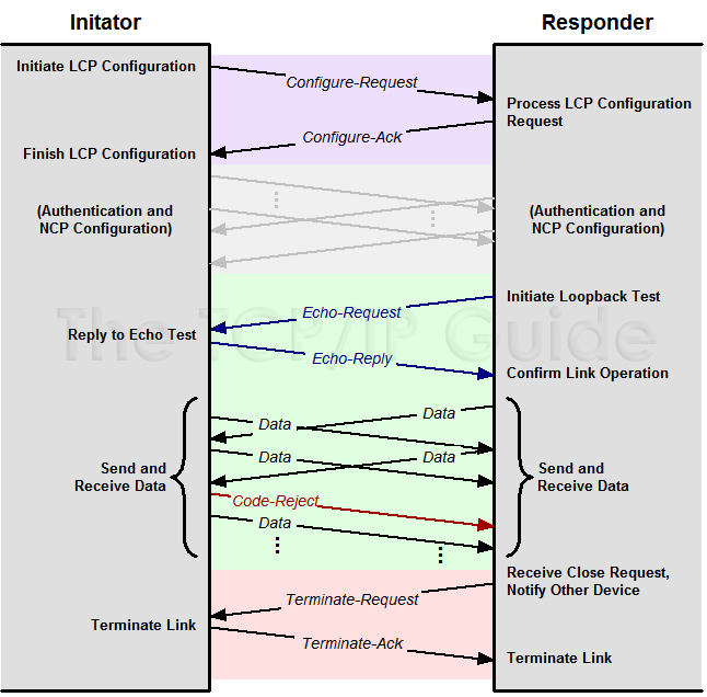
Figure 26: PPP Link Control Protocol (LCP) Message Exchanges

This diagram provides an overview of many of the message exchanges performed
by LCP during different phases of a PPP connection. Link Configuration is
here shown as a simple exchange of a Configure-Request and Configure-Ack.
After subsequent exchanges using other PPP protocols to authenticate and
configure one or more NCPs, the link enters the Link Open phase. In this
example, an Echo-Request and Echo-Reply message are first used to test the
link, followed by the sending and receiving of data by both devices. One
Data message is shown being rejected due to an invalid Code field. Finally,
the link is terminated using Terminate-Request and Terminate-Ack messages.


LCP Frames

Devices use LCP to control the PPP link by sending special LCP messages
across the physical link between them. These messages are called both LCP
packets and LCP frames; while the standard uses "packet", the term "frame"
is preferred because layer two messages are normally called frames. There
are eleven different LCP frame types defined in the main PPP document, which
are divided into three groups that correspond to the three link .life stages.
above. Four LCP frame types are used for link configuration, five for
maintenance and two for termination. The frame formats themselves are described
in the topic on LCP frames. Below I will discuss each of the three major
functions of LCP and how the frames are used in each.

Key Concept: The PPP Link Control Protocol (LCP) is the most important
protocol in the PPP suite. It is responsible for configuring, maintaining
and terminating the overall PPP link. The two devices using PPP employ a set
of LCP frames to conduct LCP operations.


LCP Link Configuration

Link configuration is arguably the most important job that LCP does in PPP.
During the Link Establishment phase, LCP frames are exchanged that enable
the two physically-connected devices to negotiate the conditions under which
the link will operate. Figure 27 shows the entire procedure, which we will
now examine in detail.

The process starts with the initiating device (let's call it device A, yeah,
isn't that original) creating a Configure-Request frame that contains a
variable number of configuration options that it wants to see set up on the
link. This is basically device A's .wish list. for how it wants the link
created.
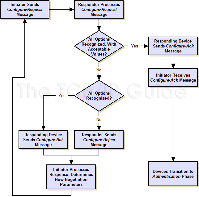
Figure 27: PPP LCP Link Configuration Process

This flowchart shows in more detail the negotiation process undertaken to configure the link by LCP. This process begins when the PPP link enters the Link Establishment phase. After successful configuration, the connection transitions to the Authentication phase.


The main PPP document (RFC 1661) defines a number of different configuration
options that the initiator can specify in this request. Any one of these can
be included and if so, filled in with the value corresponding to what device
A wants for that option. If absent, this means device A is neither requesting
nor specifying that option. The six options are:

    * Maximum-Receive-Unit (MRU): Lets device A specify the maximum size
    datagram it wants the link to be able to carry.

    * Authentication-Protocol: Device A can indicate the type of authentication
    protocol it wishes to use (if any).

    * Quality-Protocol: If device A wants to enable quality monitoring on
    the link, what protocol to use (though there is only one currently
    defined: LQR).

    * Magic-Number: Used to detect looped back links or other anomalies in
    the connection.

    * Protocol-Field-Compression: Allows device A to specify that it wants
    to use .compressed. (8 bit) Protocol fields in PPP data frames instead
    of the normal 16 bit Protocol field. This provides a small but free
    savings (one byte) on each PPP frame. Note that this has nothing to do
    with the compression feature offered by CCP. See the PPP general frame
    format topic for more on this feature.

    * Address-and-Control-Field-Compression (ACFC): The same as the option
    just above but used to compress the Address and Control fields, again
    for small bandwidth savings. Again, see the PPP general frame format
    topic for more.

Other options may also be added to this list by optional feature protocols.
For example, Multilink PPP adds several options that must be negotiated
during link setup.

The other device (let's call it say. device B J) receives the Configure-Request
and processes it. It then has three choices of how to respond:

   1. If every option in it is acceptable in every way, device B sends back
   a Configure-Ack (.acknowledge.). The negotiation is complete.

   2. If all the options that device A sent are valid ones that device B
   recognizes and is capable of negotiating, but it doesn't accept the values
   device A sent, then device B returns a Configure-Nak (.negative acknowledge.)
   frame. This message includes a copy of each configuration option that B
   found unacceptable.

   3. If any of the options that A sent were either unrecognized by B, or
   represent ways of using the link that B considers not only unacceptable
   but not even subject to negotiation, it returns a Configure-Reject
   containing each of the objectionable options.

The difference between a Configure-Nak and a Configure-Reject is that the
former is like device B saying .I don't accept your terms, but I'm willing
to haggle., while the latter is device B basically saying .No way Jose.. For
example, if device A tries to request PAP as the authentication protocol but
device B wants to use CHAP, it will send a Configure-Nak. If device B doesn't
support authentication at all, it will send a Configure-Reject


LCP Link Maintenance

Once the link has been negotiated, LCP passes control to the appropriate
authentication and/or NCP protocols as discussed in the PPP Link Setup and
Phases topic. Eventually the link setup will complete and go into the open
state. LCP messages can then be used by either device to manage or debug the
link:

    * Code-Reject and Protocol-Reject: These frame types are used to provide
    feedback when one device receives an invalid frame due to either an
    unrecognized LCP Code (LCP frame type) or a bad Protocol identifier.

    * Echo-Request, Echo-Reply and Discard-Request: These frames can be used
    for testing the link.


LCP Link Termination

Finally, when the link is ready to be shut down, LCP terminates it. The
device initiating the shutdown (which may not be the one that initiated the
link in the first place) sends a Terminate-Request message. The other device
replies back with a Terminate-Ack. A termination request indicates that the
device sending it needs to close the link. Like a four-year-old who tells
you he .needs to go now, bad!., this is a request that cannot be denied. J
Other LCP Messages

The standard RFC 1570, PPP LCP Extensions, also defines two new LCP message
types. The Identification message is used to allow a device to identify
itself to its peer on the link. The Time-Remaining message lets one device
tell the other how much time remains in the current session.  Relationship
Between LCP and Other PPP Protocols

Note that many of the other protocols used in PPP are modeled after LCP.
They use the same basic techniques for establishing protocol connections,
and send and receive a subset of LCP message types. They also exchange
configuration options in a similar manner. The next topic shows how the
Network Control Protocols (NCPs) are based on LCP. You will see the same
thing in looking at feature protocols such as CCP, ECP and others.


PPP NETWORK CONTROL PROTOCOLS (IPCP, IPXCP, NBFCP AND OTHERS)

One of the reasons why PPP is such a powerful technology is that it is
flexible and expandable. Even though it was originally created with the idea
of carrying IP datagrams, PPP's designers recognized that it would be
short-sighted to think so narrowly. PPP could easily carry data from many
types of network layer protocols, and on some networks, it might even be
advantageous to let it carry datagrams from different layer three protocols
simultaneously.

Allowing PPP to support multiple network layer protocols would require it
to have knowledge of each one's idiosyncrasies. If we used only LCP for link
configuration, it would need to know all the unique requirements of each
layer three protocol. This would also require that LCP be constantly updated
as new layer three protocols were defined and as new parameters were defined
for existing ones.

Instead of this inflexible design, PPP takes a .modular. approach to link
establishment. LCP performs the basic link setup, and after (optional)
authentication, invokes a Network Control Protocol (NCP) that is specific
to each layer three protocol that is to be carried over the link. The NCP
conducts a negotiation of any parameters that are unique to the particular
network layer protocol. More than one NCP can be run for each LCP link

Each of the common network layer technologies has a PPP NCP defined for it
in a separate RFC. These documents are usually named in this pattern: .The
PPP  Control Protocol.. The most common ones are
The PPP Internet Protocol Control Protocol (IPCP), The PPP Internetworking
Packet Exchange Control Protocol (IPXCP), and The PPP NetBIOS Frames Control
Protocol (NBFCP). These are the NCPs for IP, IPX and NBF (also called NetBEUI),
respectively. A separate NCP is also defined for IP version 6, the PPP IP
Version 6 Control Protocol (IPv6CP).


Operation of PPP Network Control Protocols

Each NCP operates very much like a .lite. version of LCP, as you can see by
examining Figure 28 (and comparing it to Figure 26, which shows the messaging
for LCP). Like LCP, each NCP performs functions for link setup, maintenance
and termination.only it deals with its particular type of NCP link and not
the .overall. LCP link. Each NCP uses a subset of seven of the message types
defined in LCP, and uses them in very much the same way as the message type
of the same name is used in LCP:

    * Link Configuration: The process of setting up and negotiating the
    parameters of the particular NCP link (once an LCP link is established)
    is accomplished using Configure-Request, Configure-Ack, Configure-Nak
    and Configure-Reject messages just as described in the LCP topic, except
    these ones are particular to the NCP. The configuration options are of
    course different; they are the network layer protocol parameters being
    negotiated.

    * Link Maintenance: Code-Reject messages can be sent to indicate invalid
    code values (NCP frame types).

    * Link Termination: An NCP link can be terminated using Terminate-Request
    and Terminate-Ack. (Remember that NCP links are set up within an LCP
    link; there can be more than one NCP link open, and closing NCP links
    doesn't terminate the LCP link. Also, NCP links do not need to be closed
    when an LCP link is terminated.)
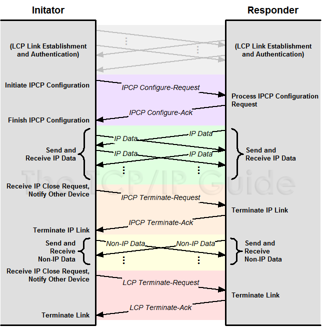 Figure 28: PPP IP Control Protocol (IPCP) Message Exchanges
The overall operation of the NCPs, such as IPCP, is very similar to that of
LCP. After LCP configuration (including authentication) is complete, IPCP
Configure-Request and Configure-Ack messages are used to establish an IPCP
link. IP Data can then be sent over the link. If the IPCP connection is no
longer needed it may be terminated, after which the LCP link remains open
for other types of data to be transmitted. It is not necessary, however, to
explicitly terminate the IPCP link before terminating the LCP connection.
Key Concept: After the primary PPP link is established using LCP, each network
layer protocol to be carried over the link requires the establishment of the
appropriate NCP link. The most important of these is the PPP Internet Protocol
Control Protocol (IPCP), which allows IP datagrams to be carried over PPP.
An Example NCP: The Internet Protocol Control Protocol (IPCP)
Let's look at the NCP for IP, IPCP. When PPP is set up to carry IP datagrams,
IPCP is invoked in the Network-Layer Protocol phase (one of the PPP phases)
to set up an IP NCP link between the two devices. The setup is carried out
using the four .Configure-. messages. For IP, there are two configuration
options that can be specified in an IPCP Configure-Request:
* IP-Compression-Protocol: Allows devices to negotiate the use of something
called .Van Jacobson TCP/IP header compression.. This compresses the
size of TCP and IP headers to save bandwidth. Thus, this is similar in
concept to the Protocol-Field-Compression and
Address-and-Control-Field-Compression (ACFC) options in LCP.
* IP-Address: Allows the device sending the Configure-Request to either
specify an IP address it wants to use for routing IP over the PPP link,
or to request that the other device supply it with one. This is most
commonly used for dial-up networking links.
Again, the receiving device can send back an IPCP Configure-Ack, an IPCP
Configure-Nak, or an IPCP Configure-Reject, just as they work in LCP. The
other NCPs are similar, but use different configuration options. After
configuration is complete, data can be sent for the layer three protocol
corresponding to the NCP negotiated. This is indicated by using the appropriate
value for the Protocol field in PPP data frames containing that layer three
data.
PPP AUTHENTICATION PROTOCOLS: PASSWORD AUTHENTICATION PROTOCOL (PAP) AND CHALLENGE HANDSHAKE AUTHENTICATION PROTOCOL (CHAP)
PPP was designed to provide layer two connectivity over a variety of serial
links and other physical layer technologies, some of which have much more
of a concern about security than others. For example, suppose you hook two
machines in your computer lab together with a serial cable and want to run
PPP between them. When one of these initiates a PPP link with the other, you
don't really need to worry about .who's calling.. On the other hand, consider
an Internet Service Provider using PPP for remote dial-in users. They generally
want to allow only their customers to connect, not just anyone.
The PPP protocol suite was designed to include the use of an optional
authentication protocol for links where authentication is important. During
basic link setup by LCP, devices can negotiate the use of an authentication
protocol. If they agree, after the LCP link is set up a series of authentication
messages are sent to verify the identity of the device initiating the link.
Only if authentication is successful can the link configuration proceed.
The PPP suite initially defined two different authentication protocols: the
Password Authentication Protocol (PAP) and Challenge Handshake Authentication
Protocol (CHAP)
Password Authentication Protocol (PAP).
PAP is a very straight-forward authentication scheme, consisting of only two
basic steps, as shown in Figure 29:
1. Authentication Request: The initiating device sends an Authenticate-Request
message that contains a name and a password.
2. Authentication Reply: The responding device looks at the name and
password and decides whether to accept the initiating device and continue
in setting up the link. If so, it sends back an Authenticate-Ack. Otherwise,
it sends an Authenticate-Nak.
Figure 28: PPP IP Control Protocol (IPCP) Message Exchanges
The overall operation of the NCPs, such as IPCP, is very similar to that of
LCP. After LCP configuration (including authentication) is complete, IPCP
Configure-Request and Configure-Ack messages are used to establish an IPCP
link. IP Data can then be sent over the link. If the IPCP connection is no
longer needed it may be terminated, after which the LCP link remains open
for other types of data to be transmitted. It is not necessary, however, to
explicitly terminate the IPCP link before terminating the LCP connection.
Key Concept: After the primary PPP link is established using LCP, each network
layer protocol to be carried over the link requires the establishment of the
appropriate NCP link. The most important of these is the PPP Internet Protocol
Control Protocol (IPCP), which allows IP datagrams to be carried over PPP.
An Example NCP: The Internet Protocol Control Protocol (IPCP)
Let's look at the NCP for IP, IPCP. When PPP is set up to carry IP datagrams,
IPCP is invoked in the Network-Layer Protocol phase (one of the PPP phases)
to set up an IP NCP link between the two devices. The setup is carried out
using the four .Configure-. messages. For IP, there are two configuration
options that can be specified in an IPCP Configure-Request:
* IP-Compression-Protocol: Allows devices to negotiate the use of something
called .Van Jacobson TCP/IP header compression.. This compresses the
size of TCP and IP headers to save bandwidth. Thus, this is similar in
concept to the Protocol-Field-Compression and
Address-and-Control-Field-Compression (ACFC) options in LCP.
* IP-Address: Allows the device sending the Configure-Request to either
specify an IP address it wants to use for routing IP over the PPP link,
or to request that the other device supply it with one. This is most
commonly used for dial-up networking links.
Again, the receiving device can send back an IPCP Configure-Ack, an IPCP
Configure-Nak, or an IPCP Configure-Reject, just as they work in LCP. The
other NCPs are similar, but use different configuration options. After
configuration is complete, data can be sent for the layer three protocol
corresponding to the NCP negotiated. This is indicated by using the appropriate
value for the Protocol field in PPP data frames containing that layer three
data.
PPP AUTHENTICATION PROTOCOLS: PASSWORD AUTHENTICATION PROTOCOL (PAP) AND CHALLENGE HANDSHAKE AUTHENTICATION PROTOCOL (CHAP)
PPP was designed to provide layer two connectivity over a variety of serial
links and other physical layer technologies, some of which have much more
of a concern about security than others. For example, suppose you hook two
machines in your computer lab together with a serial cable and want to run
PPP between them. When one of these initiates a PPP link with the other, you
don't really need to worry about .who's calling.. On the other hand, consider
an Internet Service Provider using PPP for remote dial-in users. They generally
want to allow only their customers to connect, not just anyone.
The PPP protocol suite was designed to include the use of an optional
authentication protocol for links where authentication is important. During
basic link setup by LCP, devices can negotiate the use of an authentication
protocol. If they agree, after the LCP link is set up a series of authentication
messages are sent to verify the identity of the device initiating the link.
Only if authentication is successful can the link configuration proceed.
The PPP suite initially defined two different authentication protocols: the
Password Authentication Protocol (PAP) and Challenge Handshake Authentication
Protocol (CHAP)
Password Authentication Protocol (PAP).
PAP is a very straight-forward authentication scheme, consisting of only two
basic steps, as shown in Figure 29:
1. Authentication Request: The initiating device sends an Authenticate-Request
message that contains a name and a password.
2. Authentication Reply: The responding device looks at the name and
password and decides whether to accept the initiating device and continue
in setting up the link. If so, it sends back an Authenticate-Ack. Otherwise,
it sends an Authenticate-Nak.

      Figure 29: PPP Password Authentication Protocol (PAP) Authentication

PAP works using a simple exchange of a request containing name and password
information, and a reply indicating whether or not authentication was
successful.

Simple. Now, remember what Einstein said about simplicity? PAP is another
example of something that is just too simple for its own good. Chief amongst
its flaws is that it transmits the user name and password in clear text
across the link. This is a big .no-no. in security protocols, as it means
any eavesdropper can get the password and use it in the future. PAP also
provides no protection against various security attacks. For example, an
unauthorized user could simply try different passwords indefinitely and hope
he or she eventually found one that worked. PAP also puts control of the
authentication squarely on the shoulders of the initiating device (usually
a client machine) which is not considered desirable.


Challenge Handshake Authentication Protocol (CHAP)

The most important difference between PAP and CHAP is that CHAP doesn't
transmit the password across the link. Now you may be wondering.if that's
the case, how is the password verified? Well, think of it this way. PAP works
by the initiator telling the authenticator .here's the password I know, see
if it matches yours.. CHAP does this by having each of the devices use the
password to perform a cryptographic computation and then check if they each
get the same result. If they do, they know they have the same password.  CHAP
Authentication Procedure

In CHAP, a basic LCP link is set up between the initiator (calling client)
and authenticator (generally the server that is deciding whether to grant
authentication). The authenticator then takes charge of the authentication
process, using a technique called a three-way handshake. This is a fairly
common general authentication procedure; the same basic technique is used,
for example, in IEEE 802.11 Shared Key Authentication.

The three-way handshake steps are as follows (and as illustrated in Figure
30):

   1. Challenge: The authenticator generates a frame called a Challenge and
   sends it to the initiator. This frame contains a simple text message
   (sometimes called the challenge text). The message has no inherent special
   meaning so it doesn't matter if anyone intercepts it. The important thing
   is that after receipt of the Challenge both devices have the same challenge
   message.

   2. Response: The initiator uses its password (or some other shared .secret.
   that the authenticators also knows) to encrypt the challenge text. It
   then sends the encrypted challenge text as a Response back to the
   authenticator.

   3. Success or Failure: The authenticator performs the same encryption on
   the challenge text that the initiator did. If the authenticator gets the
   same result that the initiator sent it in the Response, the authenticator
   knows that the initiator had the right password when it did its encryption,
   so the authenticator sends back a Success message. Otherwise, it sends a
   Failure message.
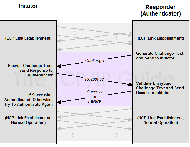
      Figure 30: PPP Challenge Handshake Authentication Protocol (CHAP) Authentication

CHAP uses a three-way handshake beginning with a Challenge from the
authenticating device (usually the remote server accessed by a host). This
message is encrypted and returned to the authenticating device, which checks
to see if the device trying to authenticate used the correct password (or
other .shared secret.).


Benefits of CHAP

You can see the beauty of this: it verifies that the two devices have the
same .shared secret. but doesn't require that the secret be sent over the
link. The Response is calculated based on the password, but the content of
the Response is encrypted and thus, much harder to derive the password from.
CHAP also provides protection against replay attacks, where an unauthorized
user captures a message and tries to send it again later on. This is done
by changing an identifier in each message and varying the challenge text.
Also, in CHAP the server controls the authentication process, not the client
that is initiating the link.

Key Concept: PPP supports two authentication protocols: PAP and CHAP. PAP
is a simple request/reply authentication protocol that is widely considered
to be inadequate since it sends the user name and password in clear text and
provides little protection against many security concerns. CHAP uses a
three-way handshake procedure and is preferred over PAP in most implementations.

CHAP itself is not perfect, but it's a heck of a lot closer to perfection
than PAP is. In fact, the IETF made a rather strong statement in this regard
when it revised the original RFC describing PAP and CHAP, and included only
CHAP in the new standard. Despite this, PAP is still used in some applications,
because it is simple. And well, some folks think they are smarter than
Einstein. J Seriously though, PAP can be fine in situations where security
is not a big deal, but CHAP is much better and still not really that
complicated.


PPP LINK QUALITY MONITORING/REPORTING (LQM/LQR)

PPP includes optional authentication in recognition of the varying security
needs of the many different kinds of links over which PPP may operate. These
links also differ greatly in terms of their quality. Just as we don't need
to worry about authentication much when two machines are linked with a short
cable, we also can feel pretty confident that data sent between them is going
to arrive intact. Now, contrast that to a PPP session established over a
long-distance telephone call. For that matter, how about PPP over a dial-up
call using an analog cellular phone?

PPP includes in its basic package a provision for detecting errors in sent
frames (a CRC field), and higher-layer protocols like TCP also include methods
of providing robustness on noisy lines. These techniques allow a link to
tolerate problems, but provide little in the way of useful information about
what the status of the link is. In some situations, devices may want to be
able to keep track of how well the link is working, and perhaps take action
on it. For example, a device experiencing too many errors on a dial-up
connection might want to cut off and retry a new call. In some cases a device
might want to try an alternate method of attachment if the current physical
link is not working well.

Recognizing this need, the PPP suite includes a feature that allows devices
to analyze the quality of the link between them. This is called PPP Link
Quality Monitoring or LQM. PPP is set up generically to allow any number of
different monitoring functions to be used, but at present there is only one,
called Link Quality Reporting (LQR). LQR works by having a device request
that its peer (the other device on the link) keep track of statistics about
the link and send them in reports on a regular basis.  LQR Setup

Before LQR can be used it must be set up, which is done by LCP as part of
the negotiation of basic link parameters in the Link Establishment phase.
The device opening the link requests link monitoring by including the
Quality-Protocol configuration option in its Configure-Request frame. Again,
LQR is the only quality protocol presently defined. The configuration option
also specifies a reporting period that indicates the longest period of time
the requesting device wants to go between receiving reports.


LQR Counters

Assuming that the negotiation is successful, LQR will be enabled. A number
of counters are set up that keep track of various link statistics, and a
timer used to regulate the sending of quality reports over the link. Each
time the timer expires a special link quality report is generated and sent
in a PPP frame over the link. These are sent using the special PPP Protocol
field hexadecimal value 0xC025.

Each counter holds information about a different statistic regarding the use
of the link. Each of these counters is reset to zero when LQR is set up and
then incremented each time a transmission is made or an event occurs that
is relevant to the counter. The statistics tracked include the following:

    * The number of frames sent/received.

    * The number of octets (bytes) in all frames sent/received.

    * The number of errors that have occurred.

    * The number of frames that had to be discarded.

    * The number of link quality reports generated.

These counters are only reset at the start of the link, so they contain
figures kept cumulatively over the life of the connection. The counters can
be used in the absolute sense, meaning that the counter value itself is
reported. Alternately, they can be expressed as relative (or delta) values,
which represent the change since the last report. This is done when a report
is received simply by subtracting the previous report's numbers from those
in the current report.  Using Link Quality Reports

LQR specifies the quality reporting mechanism, but not specific standards
for link quality, since these are so implementation-dependent. Based on the
numbers in these reports, a device can decide for itself what conclusions
to draw about link quality, and in turn what action to take, if any. For
example:

    * Some devices might decide to shut down a link if the absolute number
    of errors seen in any report reaches a certain threshold.

    * Some might look at the trend in successive reporting periods and take
    action if they detect certain trends, such as an increase in the rate
    of discarded frames.

    * Some devices might just log the information and take no action at all.

Note that LQR aggregates its statistics for all higher-layer protocols
transmitted over a particular link. It doesn't keep track of statistics for
different higher-layer protocols separately (which makes sense, since the
quality of the link shouldn't vary from one higher layer protocol to the
next).


PPP COMPRESSION CONTROL PROTOCOL (CCP) AND COMPRESSION ALGORITHMS

PPP is, of course, primarily used to provide data link layer connectivity
to physical serial links. One of the biggest problems with serial links
compared to many other types of layer one connections is that they are
relatively slow. Consider that while 10 Mbps regular Ethernet is considered
sluggish by modern LAN standards, it is actually much faster than most serial
lines used for WAN connectivity, which can be 10, 100 or even 1000 times
slower.

One way to improve performance over serial links is to use compression on
the data sent over the line. Depending on the data transferred, this can
double the performance compared to uncompressed transmissions, and can in
some cases do even better than that. For this reason, many hardware devices
include the ability to compress the data stream at the physical layer. The
best example of this is probably the set of compression protocols used on
analog modems.

Some physical links don't provide any compression capabilities, but could
still benefit from it. To this end, an optional compression feature was
created for PPP. It is implemented using two distinct protocol components:

    * PPP Compression Control Protocol (CCP): This protocol is responsible
    for negotiating and managing the use of compression on a PPP link.

    * PPP Compression Algorithms: A set of compression algorithms that perform
    the actual compression and decompression of data. Several of these are
    defined in Internet standards (RFCs). In addition, it is possible for
    two devices to negotiate the use of a proprietary compression method if
    they want to use one not defined by a public standard.

Key Concept: PPP includes an optional compression feature, which can improve
performance over slow physical links. A variety of different compression
algorithms are supported. To enable compression, both devices on a PPP link
use the PPP Compression Control Protocol (CCP) to negotiate a compression
algorithm to use. The compression algorithm is then used to compress and
decompress PPP data frames.


CCP Operation: Compression Setup

When most people talk about compression in PPP they mention CCP, which is
considered .the. compression protocol for PPP. However, CCP is actually used
only to configure and control the use of compression; it is the algorithms
that do the real work of compressing and decompressing. This .separation of
powers. provides flexibility, since it allows each implementation to choose
what type of compression they wish to use.

CCP is analogous to the Network Control Protocols (NCPs) that negotiate
parameters specific to a network layer protocol sent on the link. An NCP
lets two devices decide how they will carry layer three traffic, such as how
IPCP lets the devices determine how to carry IP. CCP lets two devices decide
how they will compress data, in the same basic way.

Similarly, just as each NCP is like a .lite. version of LCP, CCP is also
like a .lite. version of LCP. It is used to set up a compression connection
called a CCP link within an LCP link between two devices. Once established,
compressed frames can be sent between the two devices. CCP also provides
messaging capabilities for managing and eventually terminating a CCP link,
again very similar to how each network layer protocol sets up a NCP link
within LCP. A CCP link is maintained independently of any NCP links.

CCP uses the same subset of seven LCP message types that the NCPs use, and
adds two additional ones. The use of these messages for each of the .life
stages. of a CCP link is as follows, which should look very familiar if
you've already read about how the NCPs and LCP itself work:

    * Link Configuration: Like the NCPs, compression configuration is done
    once CCP reaches the Network-Layer Protocol phase. The process of setting
    up compression and negotiating parameters is accomplished using
    Configure-Request, Configure-Ack, Configure-Nak and Configure-Reject
    messages just as described in the LCP topic, except the configuration
    options are particular to CCP.

    * Link Maintenance: Code-Reject messages can be sent to indicate invalid
    code values in CCP frames. The two new message types are Reset-Request
    and Reset-Ack, which are used to reset the compression (the CCP link)
    in the event of a detected failure in decompression.

    * Link Termination: A CCP link can be terminated using Terminate-Request
    and Terminate-Ack. Again, remember that like the NCP links, the CCP link
    is set up within an LCP link, and closing it doesn't terminate the LCP
    link which controls PPP overall.


CCP Configuration Options and Compression Algorithms

CCP configuration options are used for only one purpose: to negotiate the
type of compression to be used by the two devices, and the specifics of how
that algorithm is to be employed. The device initiating the negotiation sends
a Configure-Request with one option for each of the compression algorithms
it supports. The other device compares this list of options to the algorithms
it understands. It also checks for any specific details relevant to the
option to see if it agrees on how that algorithm should be used. It then
sends back the appropriate reply (Ack, Nak or Reject) and a negotiation
ensues until the two devices come up with a common algorithm both understand.
If so, compression is turned on; otherwise, it is not enabled.

The CCP configuration options begin with a Type value that indicates the
compression algorithm. When the Type value is 0, this indicates that the
option contains information about a special, proprietary compression algorithm
not covered by any RFC standards, which can be used if both devices understand
it. Several values from 1 to 254 indicate compression algorithms that have
been defined for use with CCP. Table 30 shows the most common values of the
Type field, including the compression algorithm each corresponds to and the
number of the RFC that defines it:
Table 30: PPP Compression Control Protocol (CCP) Compression Algorithms
CCP Option Type Value |
Defining RFC |
Compression Algorithm (As Given in RFC Title) |
0 |
— |
Proprietary |
1 and 2 |
1978 |
PPP Predictor Compression Protocol |
17 |
1974 |
PPP Stac LZS Compression Protocol |
18 |
2118 |
Microsoft Point-To-Point Compression (MPPC) Protocol |
19 |
1993 |
PPP Gandalf FZA Compression Protocol |
21 |
1977 |
PPP BSD Compression Protocol |
23 |
1967 |
PPP LZS-DCP Compression Protocol (LZS-DCP) |
26 |
1979 |
PPP Deflate Protocol |
Compression Algorithm Operation: Compressing and Decompressing Data

Once an algorithm has been successfully negotiated, the compression algorithm
is used to compress data before transmission, and to decompress it once
received. To compress, the transmitting device takes the data that would
normally be put in the Information field of an uncompressed PPP frame and
runs it through the compression algorithm. To indicate that a frame has been
compressed, the special value 0x00FD (hexadecimal) is placed in the PPP
Protocol field. When compression is used with multiple links and the links
are compressed independently, a different value is used: 0x00FB. Recall that
in a regular uncompressed frame, the Protocol field indicates what layer
three protocol the data comes from; since we still need to know this, the
original Protocol value is actually prepended to the data before compression.
When the data is decompressed, this value is used to restore the original
Protocol field, so the receiving device knows what higher layer the data
belongs to.

For example, if we use IPCP to encapsulate IP data in PPP, the uncompressed
frame would have a value of 0x8021 (hex) in the Protocol field. This value
(0x8021) would be placed at the start of the data to be compressed. The
compressed data would be put in a PPP frame with a Protocol value of 0x00FD.
The receiving device would see the value 0x00FD in the Protocol field,
recognize the frame as compressed, decompress it and restore the original
frame with 0x8021 as the Protocol value. The PPP general frame format topic
covers this in more detail.

In theory, a compression algorithm can put more than one PPP data frame into
a compressed PPP data frame. Despite this, many if not most of the algorithms
maintain a one-to-one correspondence, putting each PPP data frame into one
compressed frame. Note that LCP frames are not compressed, nor are the control
frames used for other protocols. For example, a data frame carrying IP traffic
would be compressed, but a control frame for IPCP (the Network Control
Protocol for IP) would not be.

Compression can be combined with encryption; in this case compression is
done before encryption.


PPP ENCRYPTION CONTROL PROTOCOL (ECP) AND ENCRYPTION ALGORITHMS

The PPP authentication protocols PAP and CHAP can be used to ensure that
only authorized devices can establish a PPP connection. Once that is done,
PPP normally provides no other security to the data being transmitted. In
particular, all data is normally sent .in the clear. (unencrypted), making
it easy for someone who intercepts it to read. For important data that must
be kept secure, encryption prior to transmission is a good idea. This can
be done at higher layers using something like IPSec, but PPP also provides
an optional feature that allows data to be encrypted and decrypted at the
data link layer itself.

PPP data encryption is implemented using two protocol components:

    * PPP Encryption Control Protocol (ECP): This protocol is responsible
    for negotiating and managing the use of encryption on a PPP link.

    * PPP Encryption Algorithms: A family of encryption algorithms that
    perform the actual encryption and decryption of data. Several of these
    are defined in Internet standards (RFCs), and two devices can also
    negotiate a proprietary encryption method if they want to use one not
    defined by a public standard.

ECP is usually the only part mentioned when encryption in PPP is discussed.
ECP is in fact used only to configure and control the use of encryption; it
is the algorithms that do the real work. This technique allows each
implementation to choose what type of encryption they wish to use. The
original ECP defined only a single encryption method, and a couple of others
have since been added.

Key Concept: PPP includes an optional encryption feature, which provides
privacy for data transported over PPP. A number of encryption algorithms are
supported. To enable encryption, both devices on a PPP link use the PPP
Encryption Control Protocol (ECP) to negotiate which algorithm to use. The
selected algorithm is then used to encrypt and decrypt PPP data frames.

Like CCP, ECP is analogous to the Network Control Protocols (NCPs) that
negotiate parameters specific to a network layer protocol sent on the link,
but deals with how devices encrypt data rather than how they transport layer
three traffic. This also means that like the NCPs, ECP is a "lite" version
of LCP and works in the same basic way. Once an ECP link is negotationed,
encrypted frames can be sent between devices. When no longer needed, the ECP
link can be terminated.

ECP uses the same subset of seven LCP message types that the NCPs use, and
adds two more. The use of these messages for each of the .life stages. of
an ECP link is as follows:

    * Link Configuration: Like the NCPs (and also like CCP of course),
    encryption configuration is done once ECP reaches the Network-Layer
    Protocol phase. The process of setting up encryption and negotiating
    parameters is accomplished using Configure-Request, Configure-Ack,
    Configure-Nak and Configure-Reject messages just as described in the LCP
    topic, except the configuration options are particular to ECP.

    * Link Maintenance: Code-Reject messages can be sent to indicate invalid
    code values in ECP frames. The two new message types are Reset-Request
    and Reset-Ack, which are used to reset the encryption (the ECP link) in
    the event of a detected failure in decryption.

    * Link Termination: An ECP link can be terminated using Terminate-Request
    and Terminate-Ack. Again, remember that like the NCP links, the ECP link
    is set up within an LCP link, so closing it doesn't terminate the LCP
    link.


ECP Configuration Options and Encryption Algorithms

ECP configuration options are used only to negotiate the type of encryption algorithm to be used by the two devices, and the specifics of how that algorithm is to be employed. The device initiating the negotiation sends a Configure-Request with one option for each of the encryption algorithms it supports. The other device compares this list of options to the algorithms it understands. It also checks for any details relevant to the option to see if it agrees on how that algorithm should be used. It then sends back the appropriate reply (Ack, Nak or Reject) and a negotiation ensues until the two devices come up with a common algorithm both understands. If so, encryption is enabled, and otherwise, it is left turned off.

The ECP configuration options begin with a Type value that indicates the encryption algorithm. When the Type value is 0, this indicates that the option contains information about a special, proprietary encryption method not covered by any RFC standards, which can be used if both devices understand it. Values in the range from 1 to 254 indicate encryption algorithms that have been defined for use with ECP; at present, only two are defined. Table 31 shows the values of the Type field, including the encryption algorithm each corresponds to and the number of the RFC that defines it:
ECP Option Type Value |
Defining RFC |
Encryption Algorithm (As Given in RFC Title) |
0 |
— |
Proprietary |
2 |
2420 |
The PPP Triple-DES Encryption Protocol (3DESE) |
3 |
2419 |
The PPP DES Encryption Protocol, Version 2 (DESE-bis) |
Encryption Algorithm Operation: Encrypting and Decrypting Data

After an encryption algorithm has been successfully negotiated, it is used
to encrypt data before transmission, and to decrypt data received. To encrypt,
the transmitting device takes the data that would normally be put in the
Information field of an unencrypted PPP frame and runs it through the
encryption algorithm. To indicate that a frame has been encrypted, the special
value 0x0053 (hexadecimal) is placed in the PPP Protocol field. When encryption
is used with multiple links and the links are encrypted independently, a
different value is used: 0x0055. Recall that in a regular unencrypted frame,
the Protocol field indicates what layer three protocol the data comes from;
since we still need to know this, the original Protocol value is actually
prepended to the data before encryption. When the data is decrypted, this
value is used to restore the original Protocol field, so the receiving device
knows what higher layer the data belongs to.

For example, if we use IPCP to encapsulate IP data in PPP, the unencrypted
frame would have a value of 0x8021 (hex) in the Protocol field. This value
(0x8021) would be placed at the start of the data to be encrypted. The
encrypted data would be put in a PPP frame with a Protocol value of 0x0053.
The receiving device would see the value 0x0053 in the Protocol field,
recognize the frame as encrypted, decrypt it and restore the original frame
with 0x8021 as the Protocol value.The discussion of the PPP general frame
format covers this more completely.

Each encrypted PPP data frame carries exactly one PPP data frame. Note that
unlike what we saw in compression, LCP frames and the control frames used
for other protocols can be encrypted. Compression can be combined with
encryption; in this case compression is done before encryption.


PPP MULTILINK PROTOCOL (MP/MLP/MLPPP)

Most of the time, there is only a single physical layer link between two
devices. There are some situations, however, when there may actually be two
layer one connections between the same pair of devices. This may seem strange;
why would there be more than one link between any pair of machines?

There are in fact a number of situations in which this can occur. One common
one is when two links are intentionally placed between a pair of devices.
This is often done to increase performance by .widening the pipe. between
two devices, without going to a newer, more expensive technology. For example,
if two machines are connected to each other using a regular analog modem and
it is too slow, a relatively simple solution is to just use two analog modem
pairs connecting the machines to double bandwidth.

A slightly different situation occurs when multiplexing creates the equivalent
of several physical layer .channels. between two devices even if they only
have one hardware link between them. Consider ISDN for example. The most
common form of ISDN service (ISDN basic rate interface or BRI) creates two
64,000 bps B channels between a pair of devices. These B channels are time
division multiplexed and carried along with a D channel on a single pair of
copper wire, but to the devices they appear as if there were two physical
layer links between devices, each of which carries 64 kbps of data. And the
ISDN primary rate interface (PRI) actually creates 23 or even more channels,
all between the same pair of hardware devices.

In a situation where we have multiple links, we could of course just establish
PPP over each connection independently. However, this is far from an ideal
solution, because we would then have to manually distribute our traffic over
the two (or more) channels or links that connect them. If you wanted to
connect to the Internet, you'd have to make separate connections and then
choose which to use for each action. Not exactly a recipe for fun, and what's
worse is that you could never use all the bandwidth for a single purpose,
such as downloading the latest 100 megabyte Microsoft security patch.

What we really want is a solution that will let us combine multiple links
and use them as if they were one high-performance link. Some hardware devices
actually allow this to be done at the hardware level itself; in ISDN this
technology is sometimes called bonding when done at layer one. For those
hardware units that don't provide this capability, PPP makes it available
in the form of the PPP Multilink Protocol (MP).


PPP Multilink Protocol Architecture

MP is an optional feature of PPP, so it must be designed to integrate
seamlessly into regular PPP operation. To accomplish this, MP is implemented
as a new architectural .sublayer. within PPP. In essence, an MP sublayer is
inserted between the .regular. PPP mechanism and any network layer protocols
using PPP, as shown in Figure 31. This allows MP to take all network layer
data to be sent over the PPP link and spread it over multiple physical
connections, without causing either the normal PPP mechanisms or the network
layer protocol interfaces to PPP to .break..
Figure 31: Multilink PPP Architecture

The column on the left shows the TCP/IP model architecture with corresponding
OSI Reference Model layer numbers. The center column shows the normal PPP
layer architecture. When Multilink PPP is used, there are separate PPP
implementations running over each of two or more physical links. Multilink
PPP sits, architecturally, between these links and any network layer protocols
to be transported over those links. (In this diagram only IP is shown, since
it is most common, but Multilink PPP can in fact work with multiple network
layer protocols, each being sent over each physical link.)

Key Concept: The PPP Multilink Protocol (MP) allows PPP to bundle multiple
physical links and use them like a single, high-capacity link. It must be
enabled during link configuration. Once operational, it works by fragmenting
whole PPP frames and sending the fragments over different physical links.


PPP Multilink Protocol Setup and Configuration

To use MP, both devices must have it implemented as part of their PPP software
and must negotiate its use. This is done by LCP as part of the negotiation
of basic link parameters in the Link Establishment phase (just like Link
Quality Reporting). Three new configuration options are defined to be
negotiated to enable MP:

    * Multilink Maximum Received Reconstructed Unit: Provides the basic
    indication that the device starting the negotiation supports MP and wants
    to use it. The option contains a value specifying the maximum size of
    PPP frame it supports. If the device receiving this option does not
    support MP it must respond with a Configure-Reject LCP message.

    * Multilink Short Sequence Number Header Format: Allows devices to
    negotiate use of a shorter sequence number field for MP frames, for
    efficiency. (See the topic on MP frames for more.)

    * Endpoint Discriminator: Uniquely identifies the system; used to allow
    devices to determine which links go to which other devices.

Before MP can be used, a successful negotiation of at least the Multilink
Maximum Received Reconstructed Unit option must be performed on each of the
links between the two devices. Once this is done and an LCP link exists for
each of the physical links, a virtual bundle is made of the LCP links and
MP is enabled.  PPP Multilink Protocol Operation

As mentioned above, MP basically sits between the network layer and the
regular PPP links and acts as a .middleman.. Here is what it does for each
.direction. of communication:

    * Transmission: MP accepts datagrams received from any of the network
    layer protocols configured using appropriate NCPs. It first encapsulates
    them into a modified version of the regular PPP frame. It then takes
    that frame and decides how to transmit it over the multiple physical
    links. Typically, this is done by dividing the frame into fragments that
    are evenly spread out over the set of links. These are then encapsulated
    and sent over the physical links. However, an alternate strategy can
    also be implemented as well, such as alternating full-sized frames between
    the links. Also, smaller frames are typically not fragmented, nor are
    control frames such as those used for link configuration.

    * Reception: MP takes the fragments received from all physical links and
    reassembles them into the original PPP frame. That frame is then processed
    like any PPP frame, by looking at its Protocol field and passing it to
    the appropriate network layer protocol.

The fragments used in MP are similar in concept to IP fragments, but of
course these are different protocols running at different layers. To PPP or
MP, an IP fragment is just an IP datagram like any other.

The fragmenting of data in MP introduces a number of complexities that the
protocol must handle. For example, since fragments are being sent roughly
concurrently, we need to identify them with a sequence number to facilitate
reassembly. We also need some control information to identify the first and
last fragments. A special frame format is used for MP fragments to carry
this extra information, which I describe in the section on PPP frame formats.
That topic also contains more information about how fragmenting is accomplished,
as well as an illustration that demonstrates how it works.